Adjustable spanner
Small enough to roll under a thumb, the worm in an adjustable spanner’s head slides the movable jaw to the width of a nut. Each turn of the worm moves that jaw by one tooth of the rack beneath it, so one spanner fits nuts of many sizes.
A jaw that slides across the head
Hold an adjustable spanner by its handle, and the head at its end has two jaws with a gap between them. One jaw is part of the head. The other slides across the head, towards the first or away from it. Under it, in an opening through the head, sits a short knurled screw called the worm. Roll the worm with a thumb. The gap opens or closes. In the US and Canada the tool is an adjustable wrench, and in Australia and New Zealand a shifting spanner, or a shifter.
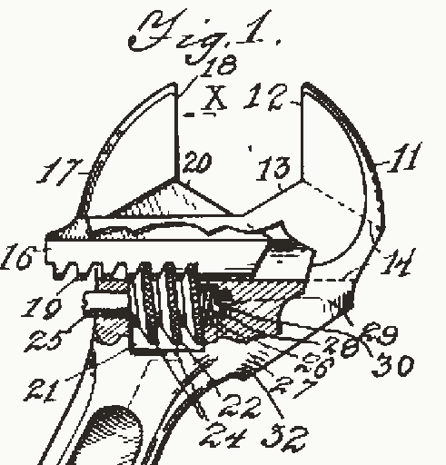
The names of the parts here are Karl Peterson’s, from his patent of 1915: the handle, the head, the fixed jaw, the movable jaw and the worm. Under the movable jaw, a bar that Peterson calls its extension slides in a slot through the head. A rack of teeth runs along the bar’s underside, and the worm’s thread sits between those teeth. An 8-inch spanner is 205 mm long and opens to 27 mm. A 6-inch one, 155 mm long, opens to 20 mm.
One turn, one tooth
The worm is a short screw with a single thread. It turns in place. As it turns, its thread runs along under the rack and carries the rack’s teeth with it. For each whole turn of a single-thread worm, the part it drives moves on by one tooth. The rack’s teeth are spaced by the worm’s pitch, the distance from one ridge of its thread to the next. Each turn moves the jaw one pitch.
The head in Fig. 1 is drawn face on, with a window cut over the worm, after the words of Peterson’s patent. Its worm has a pitch of 1.8 mm. Guess, before rolling it, which way its near side must go to open the jaws, and how many turns take them from shut to 27 mm.
What the drawing shows
Fifteen turns of the worm open the jaws the full 27 mm, 1.8 mm a turn. In this drawing the worm’s near side rolls up to open them, but that depends on which way a worm’s thread is cut. Someone who had used these spanners for years asked on a home repair forum how to tell, since they still widened the jaws by mistake about half the time. One answer said to look at which way the ridges on the wheel lean, and picture which way they would push the jaw.
Pushing on the jaw does not turn the worm back. A single-thread worm generally locks, so that the part it drives cannot turn it, when its thread climbs at under 4°. The drawing’s worm, 9.2 mm across, climbs at 3.6°. Peterson also pressed a coil spring against his worm, so that the jaw “cannot get out of adjustment”, and left the end of the rack blank. The worm stops against that blank end before the jaw can run out.
Fifteen degrees, and turning it over
The jaws are not set square to the handle. Their faces lean 15° to it. Most open-end spanners have their jaws offset from the shank by the same 15°. Peterson set his handle at an angle from the face of the jaws, so that it gives “a longer sweep” in turning a nut. The 15° also gives the jaws access in confined spaces.
The angle helps where the handle has little room to swing. A nut has six flats. They come round every 60°, so jaws taken off after a 30° swing will not go back on at the angle where the swing began. Turn the spanner over, though, and its jaws sit 15° the other side of the handle. One answer on a home repair forum gives this trick for a nut that is hard to reach. Fig. 2 shows one nut with the spanner face up and turned over. On the same two flats, the two handles lie 30° apart. After a 30° swing, the spanner goes back on turned over with its handle where the swing began, and the next swing turns the nut 30° more.
Corners and flats
A pull on the handle turns the nut by its torque, which is the force times its distance from the nut’s centre, measured square to the force. The jaws hand that torque on to the nut as two equal pushes in opposite directions, one from each jaw, each square to its face. Two such pushes make a couple. Their torque is one push times the gap between their lines. On a snug fit the pushes land at the ends of the flats. With a nut 17 mm across its flats and the hand 160 mm from its centre, each jaw then pushes 16 times as hard as the hand pulls.
Set the jaws a little wider than the nut, and the spanner turns on it before they grip. Fig. 3 draws that nut in the spanner of Fig. 1, end on. The spanner is held still and the nut is drawn turned against it, which is the same motion seen from the spanner. Before you open the jaws in Fig. 3, guess the play at which the spanner slips round the nut.
What the drawing shows
The corners slip past the jaws at 2.63 mm of play, less than a sixth of the nut’s width. Long before that, the pushes leave the flats for the corners, and their lines draw closer together, so each push must grow to give the same torque. At 0.9 mm of play each push is about a fifth larger than on a snug fit, and at 2.25 mm more than two and a half times as large. The forum answer on turning the spanner over warns that a loose spanner damages the corners and so makes the slack worse. A spanner that does not fit tightly will slip and round the corners of the nut.
Which jaw, and which way to pull
Both pushes are equal. In this model neither jaw pushes harder. What the way you turn changes is where each push lands. One lands near the tip of one jaw, and the other near the root of the other jaw. A push near a jaw’s tip has a longer arm about the jaw’s root, so it bends that jaw harder than the same push near the root. With the spanner face up as in Fig. 3, tightening puts the movable jaw’s push near its tip, and loosening puts it near its root. Turned over, the spanner swaps them.
Sources differ on how much that matters. The US Navy’s manual on tools says to place the spanner so the force falls on the fixed jaw’s side, and never so the pull falls on the adjustable jaw. Wikipedia gives a reason, that the movable jaw is held only by the flat faces either side of its guide slot, so it stands bending less well than the fixed one. Peterson braced the root of his fixed jaw, where, he wrote, the jaw “is weakest and most likely to break”. A maker’s leaflet of 2004 says its spanners are stronger than the ISO standards demand, “whichever drive direction is used”.
From Coes to Peterson
Spanners that can be set to a nut are older than the worm and rack drawn here. Loring Coes, of Springfield, Massachusetts, was granted US Patent 2,054, dated 16 April 1841, for an improvement in adjusting hand-wrenches, which his patent treats as a thing already in use. His lower jaw slides back and forth along the shank, square to the jaws, moved by a screw beside the shank that turns with a milled nut. At the Royal Agricultural Society of England’s show at Southampton in 1844, the judges thought a silver medal due to Richard Clyburn, of Uley, for his “adjusting spanners, or wrenches”. They found them “much more convenient than the common monkey spanner”. Their report does not say how his spanners adjusted.
Enoch Harris, of Quincy, Illinois, filed on 25 March 1885 for a wrench whose movable jaw runs along the head towards the fixed jaw or away from it, driven by a feed-screw with a thumb-piece. His handle could be set at any angle, and his patent is dated 22 September 1885. Karl Peterson, of Jamestown, New York, filed on 18 January 1915 for the worm and rack of Fig. 4. He was granted US Patent 1,133,236 on 23 March 1915, assigned to the Crescent Tool Company. A leaflet of 2004 from the Swedish maker Bahco says that firm was the first to bring in the adjustable wrench, patented in 1892, the work of Johan Petter Johansson, a blacksmith of Enkoping. Coes’s patent and the Southampton report are both older.
What the drawings leave out
The sizes are the drawing’s own. The 27 mm opening and the 15° angle are a maker’s. The worm’s pitch, width and length, the nut, the hand’s 160 mm and every shape are not, and no source gives the pitch of a spanner’s worm or the force it takes to turn a nut. The thread in Fig. 1 is cut so its near side rolls up to open the jaws, and real spanners differ. Fig. 1 also leaves out the screw the worm turns on and the spring beside it, and draws the worm’s knurl as its thread alone. Fig. 3 leaves out the window over the worm.
The model in Fig. 3 treats the jaws and the nut as rigid and smooth. It leaves out friction, which lets real jaws hold a little off square. It leaves out the hand’s pull itself, which the bolt takes, and the spring of the jaws, which lets them open a little under load. Its nut turns until two corners touch the faces, and it puts each push at a corner, as a point, where a real corner wears round. The pushes are counted in times the hand’s pull at the drawing’s 160 mm, so a grip farther out needs less pull for the same pushes. Moving the scale back runs the drawing backwards, though a rounded corner stays rounded.
Sources
Read in November 2026.
- K. Peterson, US Patent 1,133,236, “Wrench”, 23 March 1915, for the parts, the worm and rack, the angled handle and Fig. 4. (US Patent 1,133,236, 1915, Fig. 1. Public domain.)
- L. Coes, US Patent 2,054, “Method of constructing screw-wrenches”, 16 April 1841.
- E. Harris, US Patent 326,868, “Wrench”, 22 September 1885.
- J. Parkes, “Report on the exhibition of implements at the Southampton meeting, in 1844”, Journal of the Royal Agricultural Society of England, volume 5, 1845, for Clyburn’s medal.
- Bahco, “Adjustable wrenches”, a leaflet of January 2004 first published on bahco.com, read in the archived copy of 15 October 2006, for the sizes, the 15° jaws, the strength and the firm’s own account of 1892.
- US Navy, “Tools and Their Uses”, NAVEDTRA 14256, June 1992, for the fixed jaw, the fit and the 15° of open-end spanners.
- OpenStax, “College Physics 2e”, section 9.2, for torque.
- D. W. Baker and W. Haynes, “Engineering Statics: Open and Interactive”, section 4.5, for the couple.
- Course notes, “Worm gear”, for one tooth a turn.
- KHK, “Worm gear pair”, technical pages, for when a worm locks.
- Wikipedia, “Adjustable spanner”, for the tool’s other names and its movable jaw’s guide slot.
- Home Improvement Stack Exchange, “Adjustable wrench use, how to quickly determine which way to turn the wheel”, October 2016. User report.
- Home Improvement Stack Exchange, “Turning a hard to access nut?”, March 2019. User report.
The type is Playpen Sans by TypeTogether, under the SIL Open Font License 1.1.