Drain trap
Beneath a sink or a basin, the waste pipe dips into a bend that keeps back some of the last water to pass through it. That water, the seal, stops air from the drain coming up into the room.
Water left in the bend
The pipe from a basin’s waste hole bends down and up again before it runs off toward the drain. The bend is the trap, also called a P-trap or a U-bend. Approved Document H, the guidance for building work in England, asks for one at every point where water goes into the drains, “to prevent foul air from the system entering the building”. For a washbasin it gives a trap 32 mm across, with a seal 75 mm deep. It wants each trap removable, or fitted with a cleaning eye, so that a blockage can be cleared. New York City’s plumbing code asks every trap for a seal of 2 to 4 inches, which is 51 to 102 mm.
The New York code also says how a seal is measured. It is the height of the weir above the top of the dip. The weir is the lip in the outlet where water spills over toward the drain. The dip is the lowest point of the wall that hangs down between the two sides of the bend. Air from the drain can reach the basin only by getting under that wall. Water above the dip blocks it.
The trap in Fig. 1 is a basin’s, cut lengthways, at the two sizes the English guidance gives. In 2013 a Reddit user asked in r/explainlikeimfive why gravity does not keep the water stuck in the bottom of the bend. Guess how much water a dry trap like this one takes before any of it goes on toward the drain. Then tip the jug.
What the drawing shows
Filling a dry trap
This trap takes 170 mL. None goes on until it is full. The first 49 mL lie in the bottom of the bend, below the dip, and air from the drain still passes over them. After that the two sides rise together. They join under the dip. The air above each side presses down alike, so neither side can stand higher than the other. When the outlet side reaches the weir, the next drop runs over it. The level then stays at the weir, and of the jug’s 250 mL, 80 mL goes down the pipe.
Water poured in lifts both sides, so what stands above the weir has nowhere to go but over it. One reply on the Reddit thread put it down to “the weight of the water above”. Another credited inertia, and a third reader answered that inertia had nothing to do with it. After a basin has drained, its trap holds water up to the weir again.
A full pipe pulls
Let a full basin go at once, and its water can fill the pipe beyond the trap from wall to wall. That water falls on toward the stack, the upright pipe that the branches drain into. Until air reaches it, the falling water pulls on the water in the trap behind it, as in a siphon. McAlpine’s catalogue calls this state “syphonic conditions”, with “negative pressure” in the pipe. Edward D. Van Denberg, of Reading, Pennsylvania, wrote in his patent of 1913 that “it frequently happens that the water is entirely siphoned from the waste pipe and trap”. The foul gas then had a way into the basin.
Approved Document H keeps the pull small by keeping the pipe short. A pipe serving up to three basins may run without a vent for 1.7 m at a fall of 18 to 22 mm per metre. It may run 1.1 m at up to 44, or 0.7 m at up to 87. At their steepest those pipes fall 37.4, 48.4 and 60.9 mm. Each falls less than the seal. Longer or steeper pipes need a vent: a pipe to the outside air, a ventilating stack or an air admittance valve.
Fig. 2 carries the trap of Fig. 1 on to a pipe that drops into a stack. In the drawing, a pipe full of water that falls a given height before air reaches it pulls on the trap with that height of water at most. The drop starts at the 37.4 mm of the English guidance. Guess how deep it must be to take the whole seal, then let a full basin go.
What the drawing shows
Where the seal breaks
It takes a drop as deep as the seal itself, 75 mm. A shorter drop pulls the basin side of the trap down by the height of the drop, because the outlet side cannot rise above the weir. The water it gives up spills over. Then the pull stops. The two sides settle level, about halfway. After 37.4 mm the seal left is 56 mm deep, and 30 mL has gone. The other two basin pipes in the guidance leave 51 and 45 mm. All three keep more than the 25 mm the guidance asks a trap to keep in use.
At 75 mm or more, the basin side reaches the dip while the water is still falling. Air gets in under the dip. The falling water carries the outlet side’s water away with it. Only 24 mL stays, lying 12 mm below the dip, and the drain’s air can pass over it.
The New York code wants a vent joined above the weir, and not within two pipe diameters of it. The vents must keep any seal from feeling a pressure difference of more than 1 inch of water, 249 pascals. Choose the vent in Fig. 2: the falling water now draws air down the vent, and the trap keeps all 75 mm at any drop. McAlpine’s Silentrap puts a valve on the trap for the same job. Under “negative pressure” the valve rises, and air is drawn into the pipe.
Water kept back for later
Van Denberg’s answer was a pocket. His drawing, Fig. 3, shows it on the outlet side of the bend under a wash basin. Its mouth is its lowest point, and a lip over the mouth reaches part way across the pipe. When suction draws water up the outlet side, the lip turns some of it into the reservoir and holds it there. When the suction ends, and air comes in through the basin, the held water falls back into the trap and seals it again. His claims say the reservoir keeps that water through siphoning after siphoning.
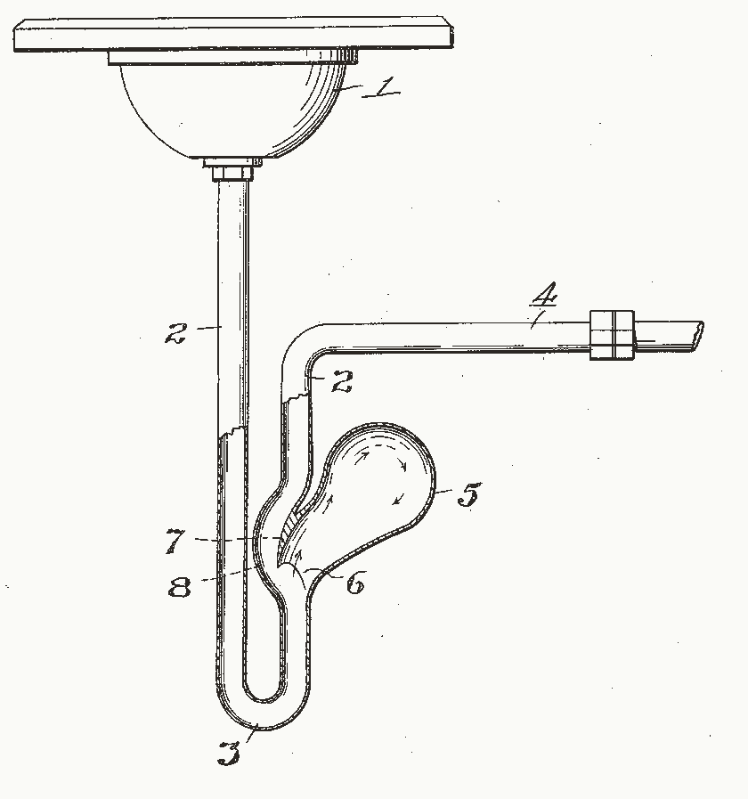
McAlpine sells resealing bottle traps that aim at the same end. Under syphonic conditions their bypass columns let air in through the inlet, which breaks the siphon, and “the remaining water falls back to reseal the trap”. McAlpine says the two differ in the path of the air. The bottle trap draws it through its water seal, and the Silentrap through its valve, which the firm says ends the gurgling. New York’s code forbids S traps and bottle traps, traps with partitions inside, and traps that need moving parts to keep their seal. The bend began as Alexander Cumming’s S-pipe of 1775, and Thomas Crapper later made it into the U-bend.
A trap nobody uses
A trap can also dry out when nobody uses it. In 2012 a householder with a shower on the lowest floor of a tri-level home shined a flashlight down its drain and asked on the Stack Exchange site for home repairs. Its water stood low enough to let sewer gas in. The accepted answer blamed evaporation, in a shower seldom used, or a blocked vent, which lets water going down the drain siphon the trap dry.
New York’s code wants traps that may dry out kept topped up, for example by a trap seal primer valve that feeds them water. Kojima and Sakaue, at Meiji University, weighed water evaporating from upright tubes indoors, with doors and windows shut, in 2016 and 2017. It went faster from wider tubes. It went faster too where the water stood nearer the open top. With 20 or 30 cm of empty tube above the water, they found it extremely small. They wrote that no reliable formula had existed for the seal water of a trap. McAlpine’s MacValve, a membrane valve that holds no water, cannot dry out at all.
What the drawings leave out
The sizes are the drawing’s own. The bend’s curve, the walls, the jug, the basin, the vent and the stack follow no source, and both sides of every trap here have the same bore. The figures also move the water slowly. Their arrows mark where water and air move, not how fast. Real water has speed, which can carry more of it over the weir, and the pipe has friction, which makes the pull weaker than a full pipe’s height. The drop in Fig. 2 also stands in for a long pipe with a gentle fall. The longest basin pipe in the guidance, 1.7 m long, falls 37.4 mm at its steepest, and the figure turns that fall into one short drop.
Only the trap’s bore and seal come from the English guidance. It also tests pipes another way, with air. They must hold a push of 38 mm of water for 3 minutes, and every trap must keep at least 25 mm of seal.
Sources
Read in November 2026.
- HM Government, Approved Document H: drainage and waste disposal, 2015 edition, for use in England: trap sizes and seals, the pipes that need no vent, vents and the air test.
- New York City Department of Buildings, 2022 New York City Plumbing Code: its definitions, its chapter on vents and its chapter on traps.
- McAlpine & Co., two catalogue sections in stockists’ copies: plastic traps, for the Silentrap, resealing bottle traps and MacValve, and technical details, for its table from BS EN 12056-2.
- E. D. Van Denberg, US Patent 1,069,655, “Antisiphon-trap”, 5 August 1913, which gives Fig. 3.
- Kerry Grist, Science Museum, “A flushing story”, for Cumming and Crapper and the name U-bend.
- T. Kojima and K. Sakaue, their study of evaporating seal water, CIB W062 Symposium, 2017.
- r/explainlikeimfive, “ELI5: How does water get past the u-shaped ‘trap’ under a sink?”, November 2013, via the Arctic Shift archive. User report.
- Home Improvement Stack Exchange, “What could be causing the low water level in my shower trap?”, August 2012, with the answer it accepted. User report.
- Home Improvement Stack Exchange, “Transparent P-Trap to help diagnose smell issue is wrong size”, January 2023. User report.
The type is Playpen Sans by TypeTogether, under the SIL Open Font License 1.1.