Egg beater
Cranking a rotary egg beater turns a large toothed wheel, which spins two pinions, each carrying a beater with wings of wire or sheet metal. The beaters turn opposite ways, several times per turn of the crank, and their wings pass between each other without touching.
A wheel set on edge
A rotary egg beater of sheet metal, made between 1908 and 1915, has a steel crank wheel standing upright on the upper part of its frame. The wheel sits between two smaller cog wheels, which turn the mixing parts when the crank goes round. The mixing parts are two bulbs, each of four wings of bent sheet metal. Its crank grip is coiled wire. The whole beater measures 2 7/8 by 9 7/8 by 3 1/8 inches. One hand grips the handle of an egg beater, or eggbeater, while the other turns the crank.
The patent of 7 July 1908 is US 892,856, granted to Earnest W. Ladd of Washington in the District of Columbia. Ladd stamps his frame from sheet steel, with a handle at one end and a boss in the middle to carry the drive wheel. The wheel is a disc of sheet metal slit inward from its edge at frequent intervals. Each piece between two slits is bent or twisted at an angle to the disc, and those pieces are the teeth. An ordinary handle, also of sheet metal, is fixed to the wheel as its crank and bent so that it clears every other part on its way round.
Teeth between two pinions
Ladd places the wheel so that its teeth come between the teeth of both pinions, one pinion either side of the wheel, and mesh with both. Each pinion tops a beater. The two pinions do not mesh with each other, although their teeth come close. Ladd adds that they guide and steady the wheel all the way round, as well as driving the beaters.
Fig. 1 follows his drawing. Its left half shows the beater from the front, with the wheel face on and the front pinion side on below it. On the right, at twice the scale, both pinions are cut across and seen from above, and the wheel’s lowest teeth pass between them. Before you turn the crank, guess how many times a beater goes round for one turn of it.
What the drawing shows
Each beater goes round 4.56 times. Ladd’s words give no tooth counts, so the counts come from his drawing. His wheel has 41 teeth, found from the angle between neighbouring teeth round his Fig. 1. His pinions are drawn side on, which hides their teeth, but each is about nine and a half of the wheel’s tooth spaces round, and the model gives it 9. For two gears in mesh the turns go in the ratio of their teeth. So 41 to 9 makes 4.56, and a quarter turn of the crank makes 1.14.
The pinions turn opposite ways because of where they sit. A tooth low on the wheel pushes on the side of each pinion that faces the wheel, and it pushes both the same way. Pushed the same way on their facing sides, the two turn opposite ways at the same speed. In every position you can reach, one or two of the wheel’s teeth are in mesh with each pinion.
Wings an eighth of a turn apart
Ladd gives each beater two main blades and two collateral blades that branch from them, set in opposite pairs. The two beaters, he writes, interlace without interfering when they turn opposite ways. By his account more blades work better, and because they interlace, the room they need hardly grows. His Fig. 6 looks up at the two sets from below. Each set is a cross. One cross is turned an eighth of a turn from the other.
Fig. 2 cuts both beaters across at their widest and looks down on them, with the front beater nearer you. Each dashed ring shows how far a beater’s wings reach, and the two rings overlap. Guess whether two wings will ever meet in the overlap as the crank goes round.
What the drawing shows
No two wings ever meet. Both beaters turn at the same speed, so the eighth of a turn between them never changes. Whenever a wing of one beater points at the other spindle, the other beater’s wings stand an eighth of a turn to either side of it. While the crank goes round once, a wing goes between two wings of the other beater 36 times. Set one pinion a tooth out, a ninth of a turn, and the model’s wings already touch before the crank moves.
Turner Williams, who patented an egg-beater with two frames turning opposite ways in 1870, gave a reason for the overlap. The liquid “cannot partake of the revolving motion” of the frames, he wrote, and so cannot escape their beating, as it does in other egg-beaters.
Collier and the Monroes
Ralph Collier of Baltimore, Maryland, patented a rotary egg-beater on 23 December 1856. He wrote that beating eggs by hand, with a fork or a hand beater, was “laborious, and fatiguing”. In his beater a crank turns a bevel pinion and a bevel wheel, which give the agitators what he calls an accelerated motion. The agitators are stirring paddles of small rigid wire.
On 19 April 1859 James F. Monroe of Fitchburg, Massachusetts, and Edwin P. Monroe of New York received a patent for an egg-beater with two beaters, one inside the other. A handle turns a large bevel wheel, and two pinions geared into it on opposite sides turn the beaters opposite ways. Their wheel already sits between two pinions, as Ladd’s does, with the beaters nested instead of side by side. A fork and a set screw fasten the frame to a table or shelf. Wikipedia says their patent was one of the earliest that the Dover Stamping Company bought, that Dover egg beaters became a classic American brand, and that by 1929 “Dover beater” was a common name.
Pinions that drive each other
Turner Williams of Providence, Rhode Island, put his two beater frames side by side. His patent, US 103,811, is dated 31 May 1870. A crank turns a face gear-wheel H, which drives the pinion C, “which, in its turn, drives the pinion C′”. Each pinion carries one frame. The frame hangs from its pinion and turns about one of the fixed wires, bent to shape, that run down from the piece B. Williams writes that the two frames occupy the same working space and turn opposite ways, each beating into the other’s area of action. As they turn, the parts of the two frames pass each other and the fixed wires with what he calls “a peculiar shearing action”.
Fig. 3 is the top of his Fig. 1. Everything hangs from the handle A. The wheel H stands on edge beside it, and the pinions C and C′ sit side by side under the piece B, where the fixed wires D are fastened.
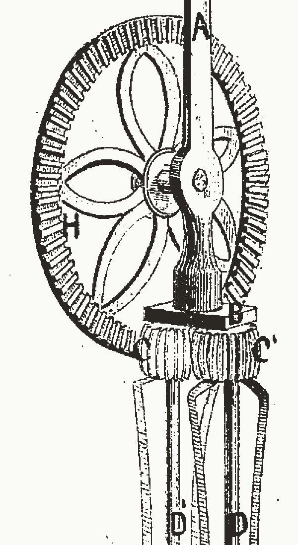
The wheel drives only C, and C drives C′. Two pinions in mesh turn opposite ways, so Williams reaches the same result as Ladd by another route. Clarence A. Taplin’s egg-beater, patented on 14 April 1903, works the same way. The teeth of its driving wheel are on the wheel’s inner face and mesh with one of two pinions, and the pinions are “in mesh with each other”. Ladd applied for his patent four years later. In his beater the wheel’s own teeth reach both pinions, and the pinions do not mesh.
A claim for 1884
Willis Johnson of Cincinnati, Ohio, patented on 5 February 1884 a machine for beating or mixing eggs, batter and the like, “used by bakers, confectioners, &c.” It stands on legs. In it a band carries power from a driving wheel to a pulley, and the beater shafts turn inside cylinders. Johnson adds that the band may be left out for a set of gear wheels.
A contributor’s page on the BBC’s A History of the World names Johnson as the egg beater’s inventor and says he patented it in 1884. The site notes that such pages come from contributors, museums and members of the public, and that the views are theirs. Wikipedia credits him only with new improvements to the egg beater in 1884.
In 2021 someone on Seasoned Advice who had neither a whisk nor an electric whisk asked whether a manual egg beater would do. The top answer said the beater in the picture counts as a whisk, and that its gearing makes a high speed easier to reach.
What the drawings leave out
The sizes are the drawing’s own. Fig. 1 keeps the proportions of Ladd’s Fig. 1, and the counts of 41 and 9 teeth come from that drawing, so a real beater may have others. His teeth are tabs bent or twisted out of the wheel’s plane, but Fig. 1 draws them flat, and cuts them as plain blocks in the view from above. Its crank is a straight strip laid over the pinion, where Ladd bends his handle out to clear it. Ladd’s beaters turn on the two sides of a wire loop, and in his Fig. 6 each wing reaches nearly to the other beater’s side. Such a wing would strike the wire. Fig. 2 keeps its wings shorter, and its spindles stand 1.3 wing reaches apart. Its wings are straight blades, where the beater of 1908 to 1915 has bulbs of bent sheet metal. Neither figure has a bowl or egg.
Sources
Read in November 2026.
- Earnest W. Ladd, US Patent 892,856, “Egg beater”, 7 July 1908, used for its words and for Figs. 1 and 2.
- National Museum of American History, its record of a Ladd egg beater, read through a copy the Internet Archive made on 7 June 2025.
- Turner Williams, US Patent 103,811, “Improved egg-beater”, 31 May 1870, used for its words and for Fig. 3.
- Ralph Collier, US Patent 16,267, “Rotary egg-beater”, 23 December 1856.
- James F. Monroe and Edwin P. Monroe, US Patent 23,694, “Egg-beater”, 19 April 1859.
- Clarence A. Taplin, US Patent 725,507, “Egg-beater”, 14 April 1903.
- Willis Johnson, US Patent 292,821, “Egg-beater”, 5 February 1884.
- Wikipedia, “Mixer (appliance)”, for the eggbeater’s other spelling and the Dover story.
- Wikipedia, “Gear train”, for the ratio of two gears in mesh.
- BBC, A History of the World, a contributor’s page on a rotary egg beater, for its claim about Willis Johnson. User report.
- Seasoned Advice, the cooking site of Stack Exchange, “Using manual egg beater to cream eggs and sugar”, May 2021, with two answers. User report.
The type is Playpen Sans by TypeTogether, under the SIL Open Font License 1.1.