Lift
Steel ropes hold up a traction lift’s car and run over a grooved wheel above the shaft to a heavy counterweight. A motor turns the wheel, so the car and the counterweight pass each other going opposite ways. Under the car, shoes wait beside the guide rails for a car that runs too fast.
Ropes over a grooved wheel
That wheel is the sheave. In a gearless traction lift a motor high in the shaft drives a large, deeply grooved sheave, and a set of parallel cables passes over it. One end of each cable holds the car up by its top, and the other holds the counterweight. Friction between grooves and cables moves the car. American Heritage says Otis first put this machine to use in 1903. Otis’s own timeline lists only “an improved gearless traction machine” that year, which is not quite the same claim.
Older lifts, or elevators, worked in other ways. Steam lifts wound their cables round drums. A tall building needed a very wide drum to hold all that cable. In a plunger hydraulic lift, the car sits on a long piston in a cylinder sunk into the ground, and water let into the cylinder pushes it up. This page draws only the traction kind. Its counterweight is the empty car plus a share of the most the car may carry. A safety alert from the International Union of Elevator Constructors, quoting the trade’s own course, says counterweights are “typically hung to counterbalance the weight of the car plus 40% of capacity load.” The drawing takes that share.
The drawing’s car weighs 1,000 kg and may carry 800, so its counterweight weighs 1,320. Guess how many blocks of load in Fig. 1 leave the motor with the least to hold.
What the drawing shows
What the motor holds
Three blocks come closest. They leave 20 kg for the motor, with the counterweight the heavier side. Four blocks tip it the other way by 80. The two sides would balance at 320 kg, which is 40% of the most the car may carry. Each block moves the balance by 100. With the car empty the motor holds 320 kg back from the counterweight’s side. Full, it holds 480 on the car’s side.
Unhook the counterweight and the motor has to hold the whole car and its load, up to 1,800 kg. With it hung, the motor’s largest job in the drawing is about a quarter of that. The drawing leaves the sheave’s other side empty then. Only the arrows and the readout change. The same safety alert says machine size may call for a counterweight of the car plus 50%. Otis had already hung a counterweight on his hoist of 1861, though not on the platform itself.
Pawls and hooked teeth
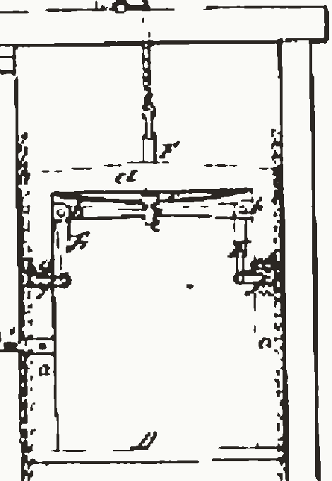
Elisha Graves Otis, of Yonkers, New York, was granted US Patent 31,128, “Improvement in hoisting apparatus”, dated 15 January 1861. Fig. 2 is part of its drawing, which names each part by a letter. Each of the two tall uprights B has a rack C down its inner side. The teeth are hooked and point upward. The platform is fixed to two uprights of its own, joined at the top and grooved to slide along the racks.
Two bent levers E are pivoted on those uprights. Their inner ends meet in an eye at the foot of a short bar F, and the hoisting rope is tied to the top of F. From there the rope runs up over pulleys and down to the drum that winds it. A spring at the foot of F tends to keep pawls, on the levers’ outer ends, in the racks. While the rope holds the platform up, its pull keeps the pawls clear. If the rope breaks, the springs throw the pawls into the teeth. Because the teeth point upward, Otis wrote, the load draws the uprights toward each other “instead of forcing them apart”, so that “casual disengagement is impossible.”
His counterweight, the counterpoise, hung from the winding drum on the side opposite the lifting rope. He claimed that arrangement in his patent. It balanced the platform “without preventing or interfering with the action of the safety mechanism”.
The catch was the patent’s second aim. Its first was a load that could be stopped at any point, with a brake put on at the same moment. A shoe presses on the machine’s working pulley whenever the platform is stopped. Both come from one hoist, worked by belts and a single hand rope.
Cutting the rope in public
Otis’s own timeline sets the story of this catch in New York in 1854, at the Exhibition of the Industry of All Nations, known as the Crystal Palace Exhibition. Standing on the platform high above the crowd, Otis has the rope cut. The platform drops a few inches, and the brake holds it. The timeline quotes him: “All safe, gentlemen, all safe.” The same timeline puts his first sale of a lift in 1853.
Both years appear in print. The Crystal Palace itself opened in 1853, on 4 July. The Science Encyclopedia gives 1853 for the show and sets it in London. Elevator World’s history of the exhibition finds it in 1854, and quotes the New York Tribune of 30 May that year. The inventor, the paper said, “as he rides up and down upon the platform occasionally cuts the rope by which it is supported.” His son Charles later wrote that the machine had “a vertical movement probably of from thirty to forty feet”. Elevator World found no record of what Otis said, so “All safe” stays unproven.
The idea was not new. While handling Otis’s application, the Patent Office found an earlier design, George Prior’s 1807 machine for mines, with springs that pushed arms into the guide rails when a rope broke.
Fast, with the rope whole
A catch that waits for a slack rope cannot help a car going too fast on a rope that holds. There was a second limit. Otis’s brake suited a slow car. A car already going down at several hundred feet a minute when its cable broke could not be stopped short without hurting the people in it. In 1878 Elisha’s son Charles answered with a brake worked by a flying-ball speed governor. That brake brought a runaway car to a gradual stop.
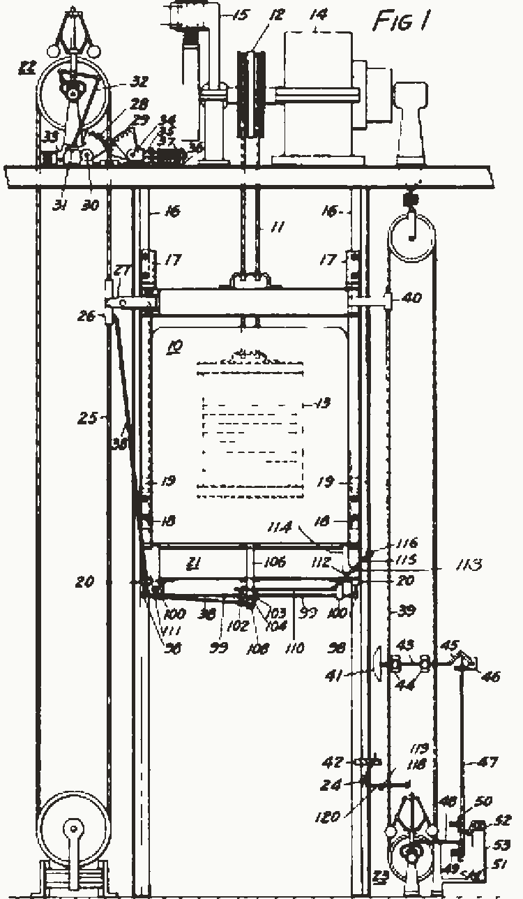
Fig. 3 shows how one such system was laid out in 1926. David L. Lindquist, of Hartsdale, New York, filed it in 1924 for the Otis Elevator Company. His first stated aim was a retarding force of a set amount, the same each time the safety acts. A governor 22 stands at the head of the shaft. Its own rope 25 runs down the shaft and round a pulley at the bottom. A hitch 26 on that rope sits in a carrier on the car, so the rope moves with the car and turns the governor. The car 10 hangs on cables 11 over a drum 12 to a counterweight 13, drawn behind it. Under the car is a beam, the safety plank 21, with a safety brake 20 at each end beside a rail. Lindquist added a second governor, 23, in the pit. It sets the brakes if the car fails to slow as it nears the lowest landing.
Flyballs and a jaw
Lindquist’s governor carries two balls on arms above its sheave. His text says what happens past the set speed. A spring-pressed latch lets go, and two jaws close on the governor rope and stop it. Fig. 4 draws a governor of that kind, with the latch and its link made into one crank. The balls hang from the top of a spindle that the sheave turns. A sleeve hangs from the balls by two links. As the spindle spins faster, the balls swing out and the sleeve rides up. The crank’s tail rests under the sleeve, and a spring pushes its jaw toward the rope.
A ball swung round a spindle on a hinged arm settles at the angle where its weight and its turning balance about the hinge. So the angle depends on how fast the spindle turns, and on nothing else in the drawing. Its car normally runs down at 1 m/s, and the balls stand 43.8° out. Guess how much faster the car in Fig. 4 must go before the jaw reaches the rope.
What the drawing shows
The answer in this drawing is a fifth more. At 1.20 m/s the balls reach 60°, and the jaw touches the rope. Below 0.91 m/s the arms rest on their stop at 30°. There the jaw is 122 mm from the rope. Between those two speeds the sleeve climbs 100 mm, while the speed grows by about a third. The tripping speed is fixed by where the jaw sits. Set nearer the rope, it would bite sooner. Once it bites, the jaw holds the rope, and the drawing keeps the speed where it tripped until Reset. The page then runs the rest by itself, for a little over a second: the car runs on, the bar under its jaws rises, and both shoes meet the rail.
Shoes on the rail
Once the governor rope is held, the car’s own motion sets the safety. The car keeps going down, so in Lindquist’s patent the rope’s hitch is pulled out of its carrier, and the car runs on past it. A second rope from the hitch then turns a lever, gears and cams, which push rods up and rock two jaw members until brake shoes 69 meet the rail. Friction then rocks the jaws further and squeezes springs 79 behind the shoes. The result, in his words, is “a gradual increase of friction or retarding force”, which then stays “substantially constant”. In Fig. 4 the held rope lifts a bar under the car’s two jaws instead.
Atwell International’s VG safety gears move their arm 44 mm in all, and “the first 30 mm brings the jaws into contact with the guide rail”. The rest is braking. The gears are set to slow a falling car at 0.6 g at the governor’s highest tripping speed. At a tripping speed of 4 m/s that gives “a nominal braking distance of 1333 mm”. Because friction varies, anything from 1,067 to 1,600 mm is within the expected limits.
When a lift going down passes a set speed, the overspeed governor locks the governor rope, and the rope sets off the safety gear that stops the lift.
Reports of a fall
On 16 November 2018 a lift at 875 North Michigan Avenue in Chicago, formerly the John Hancock Center, was widely reported to have plunged 84 floors. Five days later a reader on Engineering Stack Exchange asked how the six people inside had lived. That reader guessed the car had never really fallen. By April 2019 Otis had sent the city its final report. One of the car’s seven hoist ropes had broken. Chicago’s buildings commissioner said each rope could hold the car on its own. The car had made a “gradual lowering” from the 20th floor to the 11th, and all six were rescued. The report also said that “the elevator’s backup safety brake never engaged, indicating the elevator never traveled at an unsafe speed.” Its ropes had last been replaced in 2015.
Riders can take a sudden stop for a plunge. When a lift going up stops suddenly, the people in it feel light for a moment. A lift should have five safety devices: ropes, door locks, the governor, the safety gear and a buffer.
What the drawings leave out
The sizes are the drawing’s own. So are the weights and speeds in Figs. 1 and 4. The two views of Fig. 4 are not drawn to one scale. One rail stands for two. One bar stands for Lindquist’s lever, gears, cams and rods. His governor’s latch and link are one crank here, and the drawing ignores the spring’s push on the sleeve. Lindquist’s drum in Fig. 3 is a sheave in Fig. 1.
Governors come in other kinds as well, such as friction and drop-jaw governors, and a friction governor locks its own wheel with a latch. Once Fig. 4 trips, it holds the speed where it was, though a real car slows over a distance like those in Atwell’s example. The pace of the trip is the drawing’s own. The governor rope’s lower pulley is out of the view. Doors, their locks, the buffer and the controls are left out.
Sources
Read in November 2026.
- E. G. Otis, US Patent 31,128, “Improvement in hoisting apparatus”, 15 January 1861, used for its words and for Fig. 2.
- D. L. Lindquist, US Patent 1,581,459, “Elevator safety appliance”, 20 April 1926, used for its words and for Fig. 3.
- Otis Elevator Company, its elevator history timeline.
- Elevator World, on Otis’s improved elevator at the Crystal Palace and the years after it.
- Spencer Klaw, his 1978 history of the safety elevator, American Heritage.
- Science Encyclopedia, Elevator, history, for the year it gives.
- Atwell International, guide to its VG safety gears, version 3.0.
- Electrical and Mechanical Services Department, Hong Kong, script of its film on lift plunge.
- International Union of Elevator Constructors, safety alert on counterweights. User report.
- ABC7 Chicago, on the inspection report for the Hancock lift, 23 April 2019.
- Engineering Stack Exchange, “They survived an elevator fall. How?”, November 2018. User report.
The type is Playpen Sans by TypeTogether, under the SIL Open Font License 1.1.