Ring binder
Half of each ring in a ring binder stands on one of two narrow plates hinged along their inner edges. A bent spring plate presses the pair from the sides, so it holds the rings either shut or open. Pulled a little way apart, the rings reach a point where the plates lie flat, and past it they snap open.
Halves on two plates
Each ring of a ring binder parts at the top. Leitz’s WOW ring binder for A4 paper has two round rings, each 25 mm across, and holds 190 sheets of 80 gsm paper. Avery’s Standard Binder 03301 has round rings one inch across, which hold up to 175 sheets of letter paper, 8.5 by 11 inches, and are mounted on the back board so the pages lie flat.
The early patents call the whole thing a loose-leaf binder. William P. Pitt’s of 1904 calls it a loose-leaf book. They call the ring halves hooks, and one calls them “half rings, otherwise called hooks”. Every half is fixed to one of two narrow plates. The plates lie side by side under the rings, the length of the binder’s back. Pitt draws three pairs of hooks on one pair of plates. All of them open together. Where the holes in the paper go, and how far apart, is on the Hole punch page.
A spring plate underneath
In Pitt’s patent a spring-plate lies under the two hook-plates, and grooves along its two sides hold their outer edges. Slipping the plates in spreads it a little. So it “exerts compressive force on the plates”, from both sides, and keeps the joint between them either up or down. At that joint a V-shaped tongue on one plate fits a V-shaped groove in the other. The spring-plate is pressed down in the middle, so the joint can sink. Above the plates lies a retaining-plate, slotted where the hooks pass. Pitt left a small space between the spring-plate’s sides and the retaining-plate, so the spring-plate could spread on its own, and wrote that the space could be left out where more pressure was wanted.
Each way, a part stops the plates. Shut, the joint sits low until the tips of the hooks press together. Open, it rises until it meets the retaining-plate. In this drawing the plates stand 7° below flat when shut and 6.5° above it when open. The joint moves about a millimetre either way. Fig. 1 follows Pitt’s Fig. 5, cut across one ring. Guess how far apart the tips get before the plates take over.
What the drawing shows
The plates take over with the tips a little under 7 mm apart in this drawing, where they lie flat. Short of that, the spring-plate’s squeeze pushes the joint back down and the tips together again. Past it, the same squeeze drives the joint up and the tips apart, until the joint stops against the retaining-plate. There, Pitt wrote, the hooks are held, “leaving both hands free to handle the leaf”. Pressing them together shuts them the same way.
From a pull to a push
The spring-plate is spread furthest when the plates lie flat, since then their outer edges reach out the most. For two shallow bars joined at the top and pushed down there, the force needed rises at first and then falls to nothing as the bars reach a straight line. Past it, the force changes sign. A binder’s two plates are such a pair, held at their outer edges by the spring-plate and lifted at the joint as the tips are pulled apart. No source read gives the stiffness of a binder’s spring, so Fig. 2 gives it as a share of the largest push either way. Guess where along the way it is largest.
What the drawing shows
The largest pull comes early, with the tips only about 2 mm apart in this drawing. Shut, it is two thirds of that, since the spring-plate already squeezes the plates. From the peak it falls away to nothing at flat. Past flat the curve dips below its line, and the spring-plate drives the tips apart by itself, hardest at about 12 mm. The toggle on the Light switch page passes a centre point too before its spring takes over.
Tips that meet
The tips are the stop that ends the closing. They take the spring’s squeeze. Pitt’s hook 7 ends in a V-shaped groove, and its partner, hook 8, in a V-shaped tongue that slides into it as the ring shuts. The spring-plate keeps the pair pressed together, so the rings do not drift open in use. Pitt says it holds the hook-plates “from accidental movement”, open or closed. The same squeeze holds the joint up against the retaining-plate while they are open.
Harry C. Sterling’s patent of 1927 hinges its two plates on the rings themselves. They are “hinged together at their adjacent edges by interengagement of the ring sections as is common in the art”. His cover plate does the retaining-plate’s job. It houses the toggle plates and limits their outward movement. In Fig. 1 each half is fixed to its plate, and the two plates stay joined, so the tips always come back to the same place.
Clarence D. Trussell’s binder has no spring-plate. Instead, yokes of thick metal hold its plates under stress. The yokes do not yield, his patent of 1912 says, but the plates do: they bend a little in their own plane. That bending keeps the rings open or closed and resists any push toward the middle position. A Reddit post, a user report, says that the back of a binder’s rings flexes as they open. In Pitt’s design, that back is the spring-plate.
Levers at the ends
Pitt, of Independence, Missouri, filed his application on 1 December 1903, and his patent was granted on 20 December 1904, assigned to the Irving-Pitt Co. of Kansas City. Fig. 3 is the cross-section that Fig. 1 follows, with the open position in dotted lines.
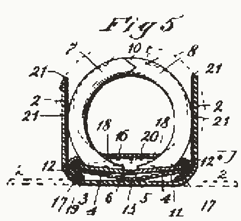
Later binders could be opened from the ends. John Schade, Jr., of Brooklyn, filed his patent on 12 June 1915 for the National Blank Book Company. It puts a booster at each end, with a toe under the plates’ meeting edges. Each booster has a handle. Pressing it lifts those edges “beyond their dead center”. Once past it, he wrote, “The bars spring to open position”. Closing the rings by hand sets the boosters back. The booster pushes the joint up from below, so the rings open without a pull at their tips. Sterling, of Syracuse, filed in 1923 for the McMillan Book Company. He calls his design “the well known toggle plate ring binder”, with “rocking actuator triggers” under the plates and a “trough-like spring plate” that he calls “commonly used in ring binders”.
What the drawings leave out
The sizes are the drawing’s own. Only the ring’s 25 mm across is taken from a real binder, Leitz’s. The plates are drawn stiff. The spring plate never bends in the drawings, because its spread, about a tenth of a millimetre at the most here, is far too small to see. Fig. 2 marks it with arrows instead.
Pitt’s tips meet in a V, and Fig. 1 cuts them square. Fig. 2 gives the push only as a share of its largest value, because no source read gives the spring’s stiffness. In the drawing the snap takes a quarter of a second. The model takes the push from the spring plate’s spread alone, and leaves out any rubbing in the grooves. Fig. 1 is cut across one ring, so the recesses in the spring plate’s flanges, where Pitt’s hooks pass, do not show. The boosters and triggers of the later patents are not drawn, nor the binder’s boards.
Sources
Read in November 2026.
- W. P. Pitt, US Patent 778,070, “Loose-leaf book”, 20 December 1904, read for the mechanism and shown as Fig. 3.
- C. D. Trussell, US Patent 1,025,170, “Loose-leaf binder”, 7 May 1912.
- J. Schade, Jr., US Patent 1,163,179, “Loose-leaf binder”, 7 December 1915.
- H. C. Sterling, US Patent 1,625,752, “Loose-leaf binder”, 19 April 1927.
- Leitz, WOW Ring Binder, 42570023, for its rings and capacity.
- Avery, Standard Binder 03301, for its rings and capacity.
- Terje Haukaas, The University of British Columbia, “Shallow Truss Snap-through”, January 2022, on the force through a snap.
- r/mildlyinteresting, “The back of binder rings flex when you open them”, July 2019, via the Arctic Shift archive. User report.
The type is Playpen Sans by TypeTogether, under the SIL Open Font License 1.1.