Scissor jack
Four arms joined in a diamond carry the load rest of a scissor jack. A screw runs across the diamond between its two side corners, and every turn draws them closer, so the diamond stands taller. The screw pulls hardest at the start, when the arms lie nearly flat.
Four arms and one screw
Folded down, a scissor jack is a squashed diamond of arms on a small base, with a load rest on top and a long screw lying across the middle. The 1.5-ton jack in Harbor Freight’s manual lists a base, two lower forks, two upper forks, a jacking head and one nut. It calls the screw a spindle rod. The scissor jack counts as a jackscrew, and as a car jack too.
The jack in Fig. 1 follows a patent jack that its inventor called a “lazy tongs type of jack”, and its labels use his names for the parts: base, arms, load rest, nuts and screw. The two lower arms meet the base at two pivots side by side, and the two upper arms meet the load rest the same way. Teeth on the arm ends mesh, so the two arms at each end swing alike. The screw has a right-hand thread at one end and a left-hand thread at the other. Each end runs through a nut at a side corner, so one turn draws both nuts in.
Guess which turn lifts the load rest further, the first or the last, and then wind the jack up in Fig. 1 to find out.
What the drawing shows
The first turn lifts the load rest 24.8 mm, and the last only 2.7 mm. Near the bottom the arms lie almost flat. There, drawing the side corners a little closer swings the arms’ far ends up a long way. As the diamond stands up, the same draw of the corners lifts it less. Half the drawn travel, from 99 mm to 208 mm, takes 8 of the 31 turns.
Why the first turns are the hardest
The screw pays for that quick rise. Leave friction out, and the work put into the screw all goes into lifting the load. The pull in the screw times how far the side corners close up equals the load times how far it rises. Statics calls this virtual work. For the diamond of Fig. 1 it makes the pull the load divided by the tangent of the arms’ angle.
Right down, with the arms at 9°, the drawn screw pulls 6.3 times the load. With them at 45° the pull equals the load, and with the load rest right up it is about half the load. A turn draws the nuts in by twice the lead of the thread, 5 mm here, so the rise for each turn falls in step with the pull. Guess how high the load rest stands once the pull has fallen to the load itself, and find the place on the curve of Fig. 2.
What the drawing shows
The pull matches the load at 264 mm, after 16.8 of the 31 turns. Harbor Freight rates its 1.5-ton jack higher as it stands taller. It may carry 3,000 lb (1,361 kg) from 14 inches (356 mm) up, 1,800 lb (816 kg) from 10 inches (254 mm), 1,200 lb (544 kg) from 8 inches (203 mm) and 900 lb (408 kg) from 6 inches (152 mm). Its manual says not to use it if it cannot extend at least 6 inches (152 mm) before it takes the load.
In 2023 the owner of a new 2-ton scissor jack asked on Stack Exchange’s site for car repairs why it struggled to lift a car of about 1.2 tons. Greasing the thread had made no difference. The one answer, from another user, said a scissor jack needs its largest force at its lowest position. In 2012 a Tesla Motors Club member saw a similar 6-inch warning on Harbor Freight’s cheapest scissor jack. To the member it explained why their old jack was so hard to crank, since the screw works at a poor advantage when the jack is almost flat.
What keeps the car up
Once the handle is let go, the load still pushes the nuts outward along the screw. That push tries to turn the screw back, the way a weight tries to slide down a slope, and a thread is a slope wound round a rod (see Screw). On a gentle enough slope, friction holds it. A thread locks itself while its lead angle is smaller than the angle whose tangent is the friction coefficient. With a coefficient of 0.16 that angle is 9.1°, and the drawn screw’s thread climbs at 3.6°, so it holds.
A well-made jack uses an acme thread, which winds easily without losing its position under load. In a 2023 r/AskEngineers thread, one reply counted it in the scissor jack’s favour that it pretty much stays where you stop turning, where hydraulic jacks can leak and slip. A floor jack lifts with a hydraulic piston pushing on a bellcrank, and a bottle jack drives a ram straight up out of its body.
Toyota’s manual for the 2024 Tacoma says: “Do not put any part of your body under the vehicle while it is supported by the jack.” It says to use a jack stand if anyone has to get under the car.
So-Lo Jack’s patents
Nils G. Larson and Frank Mossberg of Attleboro, Massachusetts, filed for a lazy-tongs jack on 23 October 1925, and US Patent 1,612,447 was granted on 28 December 1926, assigned to the So-Lo-Jack Co. of Boston. In the old lazy-tongs jack, they wrote, with the screw pulling at the corner pivots, “an excessive amount of power is required to lift the load” when the jack is down. They pivoted the nuts on the lower arms well above the corners, which they said raised the lifting power “about three-fold”. They also wrote that it “gradually increases as it is raised and the angle between the arms is reduced”.
Larson’s own patent improves on that one. He filed it on 21 December 1928. US Patent 1,736,202 was granted on 19 November 1929, assigned to So-Lo Jack Co., Inc., of Attleboro. His jack folds very low so that it can go under an axle when a tyre is flat. That matters most with balloon tyres, which let the axle drop very close to the ground. The bent-out ends of its upper arms guard the ends of the screw if the jack tips over, and it is made of sheet stock, light and strong (Fig. 3).
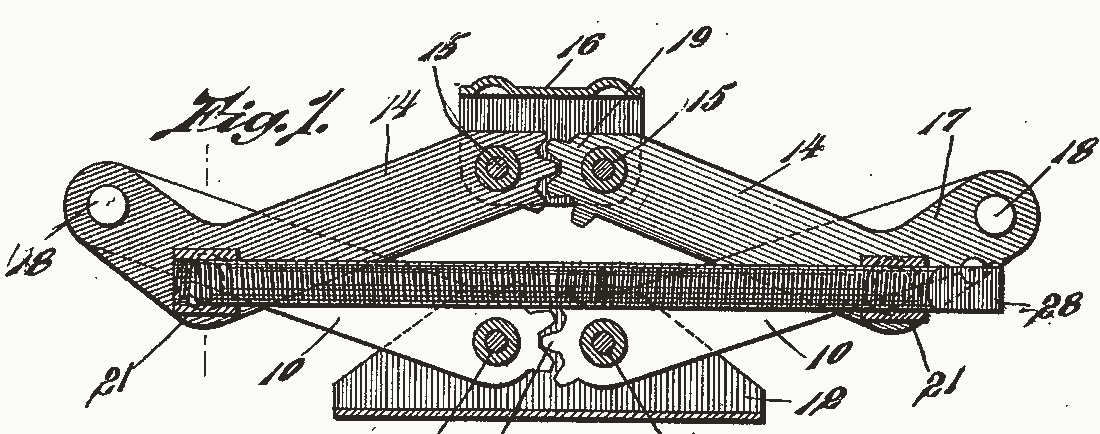
Jacks in general are older. By Wikipedia’s account, the Oxford English Dictionary first records a jack, as a machine for lifting heavy weights from below, in 1679, and Richard Dudgeon was granted a patent in 1859 for a “portable hydraulic press”, the hydraulic jack.
What the drawings leave out
The sizes are the drawing’s own. The sources give no arm length for a scissor jack, no lead or diameter for its screw, and no count of turns from bottom to top. So the drawn arms are 150 mm long, the lead is 2.5 mm and the travel 31 turns. The real 1.5-ton jack rises from 3 3/4 to 15 1/8 inches (95 to 384 mm), further than the drawn one.
Each drawn arm stands for two. Larson’s jack has one in front of the screw and one behind it. Fig. 1 sets each nut on its side pivot, where Larson sets it a little off the line through the arm’s end pivots. The pull and the rise for each turn leave out friction at the pivots and in the thread. Only the thread’s holding angle uses friction, at 0.16. The handle is a short crank on the screw’s squared end, which Larson leaves to a wrench he does not draw.
Sources
Read in November 2026.
- N. G. Larson, US Patent 1,736,202, “Load-lifting jack”, 19 November 1929, with the names of the parts and Fig. 1 of the drawing sheet.
- N. G. Larson and F. Mossberg, US Patent 1,612,447, “Load-lifting jack”, 28 December 1926.
- Harbor Freight Tools, owner’s manual for the 1.5 ton scissor jack, item 66907 (2025): its parts, ratings and warnings.
- Toyota, “If you have a flat tire”, in the 2024 Tacoma owner’s manual.
- J. Moore and contributors, “Power Screws”, Mechanics Map: the self-locking angle and the coefficient of 0.16.
- University of Illinois, TAM 211 Statics, lecture 34 (2018): a scissors jack solved by virtual work.
- Wikipedia, “Jack (device)”: other names, the acme thread, floor and bottle jacks, 1679 and Dudgeon.
- Stack Exchange, its site for car repairs, “Why does my brand new scissor jack struggle so hard to lift my car?”, April 2023, and its answer. User report.
- r/AskEngineers, “Can scissor jack be geared additionally to lift loads with less effort?”, April 2023, via the Arctic Shift archive. User report.
- Tesla Motors Club forum, “Recommended jack, for home garage or trunk?”, a post of 13 August 2012. User report.
The type is Playpen Sans by TypeTogether, under the SIL Open Font License 1.1.