Snap fastener
Pressed into its socket, the round head of a snap fastener’s stud pushes a spring aside, and the spring closes again behind the head. It then holds the head until a pull spreads it once more. How hard that pull must be depends on the slope where they touch.
A knob and a narrow mouth
A snap fastener is two small metal halves, one on each flap of whatever it closes. One half has a knob standing up from it, called the stud. The other has a hollow with a narrow mouth, the socket. Pressed together, they hold. A firm pull parts them again. The same thing goes by press stud, popper, press button and snap button. It is often put on children’s clothes, as children find it easier than a button.
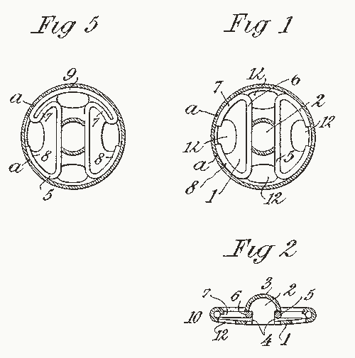
Riveted ones come in four pieces: a cap and a socket for one flap, and an eyelet and a stud for the other. The caps of DOT’s Durable fasteners, sold for tents, luggage, marine and military use, are 0.600 inch (15.24 mm) across. Others are sewn on, through holes round the rim. In the kind drawn on this page, two spring wires lie across the back of the socket, one each side of its hollow. Each reaches in to the hollow through a slit in its wall.
Over the widest part
Fig. 1 cuts the socket and the stud through the middle, across both spring wires. At rest the wires stand 2.6 mm apart, but the head is 4 mm across. So it cannot go in unless it pushes them apart. Guess where the stud will end up if you let go of it half way in.
What the drawing shows
It depends which side of the widest part the wires are on. On the way in, the domed top of the head meets them first. Its curve pushes each wire sideways in its slit, and the wire bends like a beam held at both ends. Let go up to about 2.1 mm in, and the wires push the stud back out to where it first touched them. Near the widest part the slope is too shallow to beat friction. There the stud stays where you leave it. From about 3.9 mm in, the wires slide down the underside of the head and pull the stud the rest of the way home by themselves. That last quick move is the snap. Even with the stud home, the wires stand 0.29 mm wider apart than at rest. They press on the underside of the head, and that pressure is what holds the snap shut.
The slope under the rim
How hard you must press depends on two things. One is the spring’s push across the stud, which grows with its stiffness and with how far the head has spread it. The other is the slope where the wire touches the head. A design guide to snap joints in plastic parts gives the rule. The push across is multiplied by a factor: the friction plus the slope’s tangent, divided by one minus their product. On the way out the same rule holds, with the slope under the rim, which the guide calls the return angle. A steeper slope needs more force. Friction adds to it in either direction.
Fig. 2 sets one wire against the head and plots both forces against how far the stud is in. No source gives the wire’s stiffness, so each force is a share of the hardest press. For friction the model takes 0.44, a table’s figure for brass sliding on clean, dry steel. Guess which head in Fig. 2 is harder to pull out, and by how much, before you pick the undercut one.
What the drawing shows
The round head takes the same force both ways. Its top and its underside are one curve, so its hardest pull equals its hardest press. The undercut head has a straight band at its widest and a shoulder under it at 45°. It presses in just the same, but its hardest pull is 2.8 times the hardest press, just past 4 mm in, where the wire climbs over the corner. The steep shoulder also draws the head home harder, with up to 0.43 of the hardest press against the round head’s 0.1. In this model a slope steeper than 66° to the stud’s axis could not be pulled past at all, because one minus the product falls to nothing. The guide says a return angle can make a joint impossible to part.
Springs in the stud, springs in the socket
In 1890 Edwin J. Kraetzer of Gloversville, New York, patented a glove fastener with its spring in the stud. A slit cut down from the top divided the head into two spring parts. The other flap needed only a plain eyelet. By 1906 George A. Holmes of Newton Center, Massachusetts, could write of a class of fastener “widely known as snap fasteners”, adding that “this kind of device was old”.
Elizabeth J. Smith of Larchmont, New York, put her springs in the socket. She applied in March 1916, and her patent was granted on 7 August 1917 (Fig. 3). Each of her two wires is held at both ends. She wrote that the fasteners then in use held their spring at only two points. Hers, she said, did not “become set” so readily, and lasted several times as long.
A set spring is easy to try in Fig. 1. The worn wires rest 0.3 mm further out each, so the head spreads them 0.8 mm instead of 1.4 mm. At home they no longer touch it. Nothing then holds the snap shut. A 2024 catalogue offers the sockets of DOT’s Durable range in standard, hard and easy action.
What the drawings leave out
The sizes are the drawing’s own. The wires’ stiffness comes from no source either, so no force on this page is in newtons, and the shares in Fig. 2 hold for any stiffness. The model moves each wire straight sideways where it touches the head, as a spring that pushes back in step with how far it is moved. It uses one friction figure, for sliding. The same table gives a higher one, 0.51, for starting from rest. Fig. 1 cuts across the middle of both wires; seen flat, as in Fig. 3, each is a long bar with its ends tucked under the rim. The stud is drawn solid, though Kraetzer’s was struck up from sheet metal. The cloth, the thread and the rivets are left out. So is a pull at an angle, which lifts one side first. In the model the head stays centred between the wires and moves straight along its axis.
Sources
Read in November 2026.
- E. J. Smith, US Patent 1,236,116, “Snap-fastener”, 7 August 1917, for the socket and its springs, and shown as Fig. 3.
- E. J. Kraetzer, US Patent 424,795, “Glove-fastener”, 1 April 1890, for the spring in the stud.
- G. A. Holmes, US Patent 875,816, “Snap-fastener”, 7 January 1908.
- Morito Scovill Americas, DOT industrial catalogue, 2024, for the cap’s size and the socket’s action.
- Bayer MaterialScience, “Snap-Fit Joints for Plastics: A Design Guide”, for the rule of the slope and the return angle.
- The Engineering ToolBox, “Friction and Friction Coefficients for various Materials”, for brass on steel.
- Wikipedia, “Snap fastener”, for the other names and the four pieces.
The type is Playpen Sans by TypeTogether, under the SIL Open Font License 1.1.